How to check if BMS is working?CategoriesTechnology Blogs

How to check if BMS is working?

How to check if BMS is working?

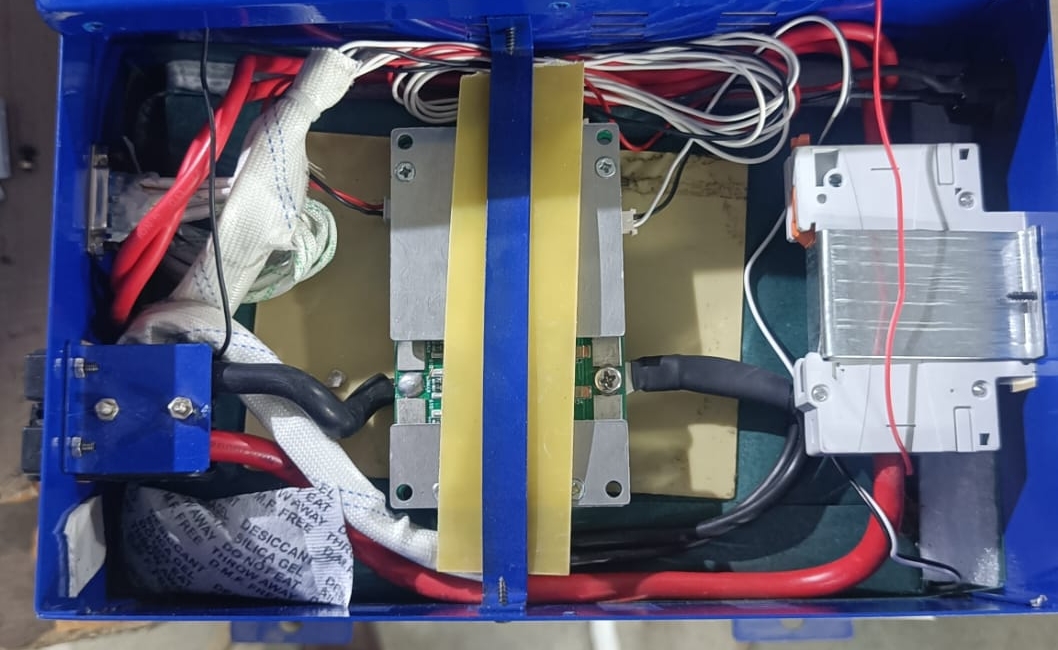
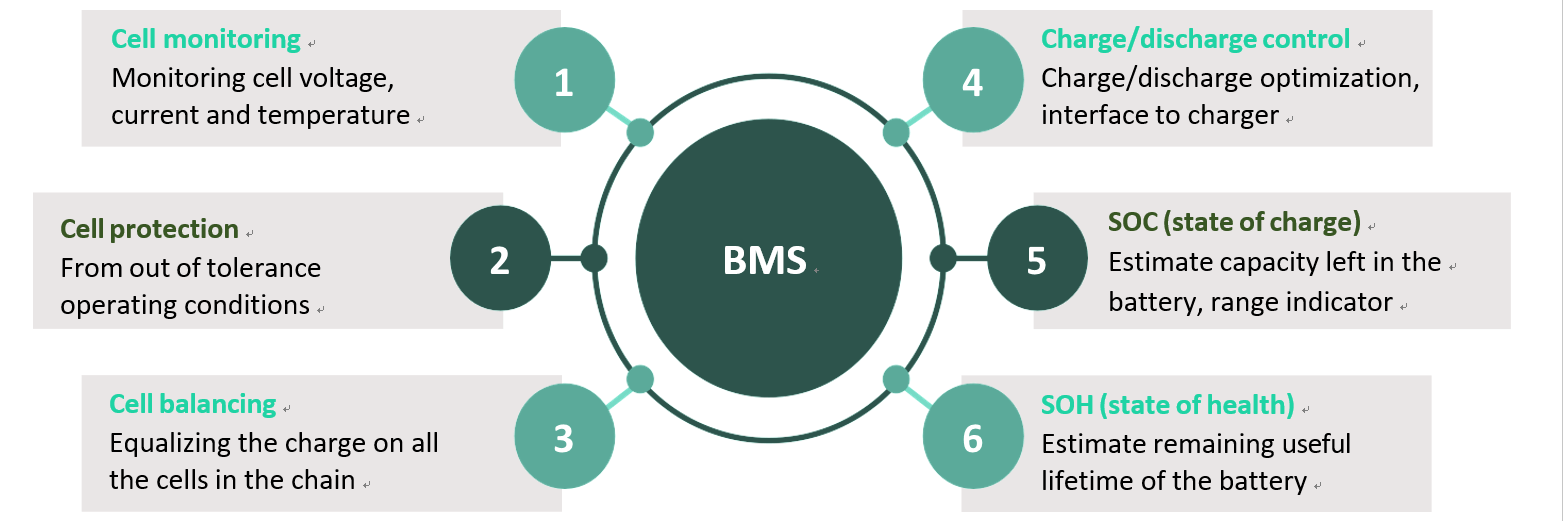
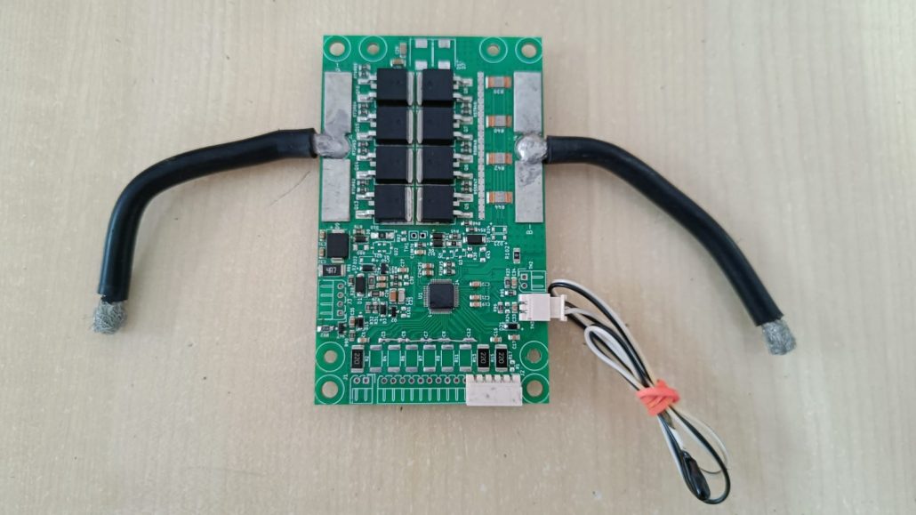
A BMS PCB, or Battery Management System Printed Circuit Board, is the heart of a BMS. It’s an electronic board with various components that work together to monitor and control a battery pack. Here’s a breakdown of how it functions:

How to check if BMS is working?

How to check if BMS is working?

Monitoring:

BMS PCBA monitoring refers to the specific process of tracking and analyzing data collected by the BMS printed circuit board (PCBA). This data is crucial for ensuring the safe and efficient operation of the battery pack.

Here’s a closer look at what BMS PCBA monitoring typically involves:
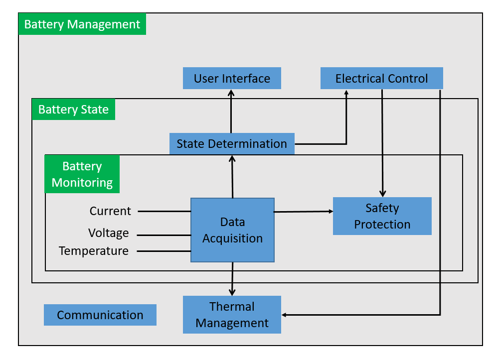
Data Acquisition:

  • The BMS PCBA continuously collects data from various sensors, including:
    • Cell voltages – monitors the voltage of each cell in the battery pack.
    • Current – tracks the current flowing into (charging) or out of (discharging) the battery.
    • Temperature – measures the temperature of the battery pack.

Data Analysis:

  • This collected data is then fed into the microcontroller on the PCBA.
  • The microcontroller analyzes the data against pre-defined thresholds for safe operation.
  • It checks for:
    • Overvoltage or undervoltage of individual cells or the entire pack.
    • Excessive charging or discharging currents.
    • Temperatures exceeding safe limits.

How to check if BMS is working?

Alerts and Actions:

  • If any parameter falls outside the safe zone, the BMS PCBA can trigger alarms or take corrective actions:
    • Alerts might be visual indicators on the device itself or transmitted to external systems for monitoring.
    • Corrective actions can involve:
      • Disconnect the battery from the charger or load to prevent damage.
      • Initiating cell balancing to equalize voltages between cells and improve battery health.

Additional Monitoring Features:

  • Depending on the BMS PCBA complexity, monitoring can extend beyond basic parameters:
    • State of Charge (SOC): This estimates the remaining capacity in the battery.
    • State of Health (SOH): This indicates the overall health and degradation of the battery over time.
    • Data logging: The BMS PCBA might store historical data on battery performance for further analysis.

By effectively monitoring the BMS PCBA data, you can gain valuable insights into the battery’s health and performance. This allows for:

  • Early detection of potential issues: Identifying problems before they cause damage can prevent costly repairs or downtime.
  • Predictive maintenance: Monitoring data can help predict when maintenance is needed, optimizing battery life and performance.
  • Improved safety: By ensuring the battery operates within safe limits, BMS PCBA monitoring minimizes safety risks associated with battery failures.

How to check if BMS is working?

Overall, BMS PCBA monitoring plays a vital role in ensuring the safe, reliable, and efficient operation of battery packs across various applications.

  • The BMS PCB continuously monitors important battery parameters like:

    • Voltage of individual cells and the entire pack
    • Current flowing in and out of the battery
    • Temperature of the battery pack
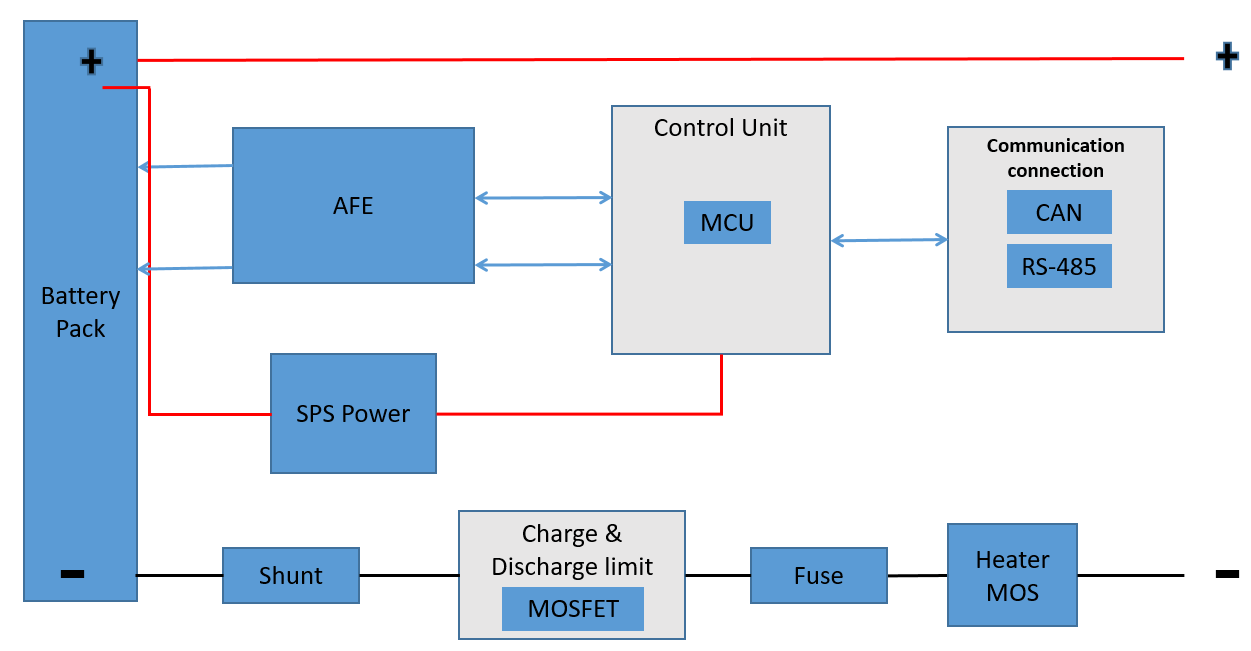
  • Sensors on the PCB collect this data and send it to the brain of the system:

Control and Protection:

BMS PCB control and protection are the two key functions that work together to safeguard your battery pack and optimize its performance. Here’s a detailed explanation of each:

Control:

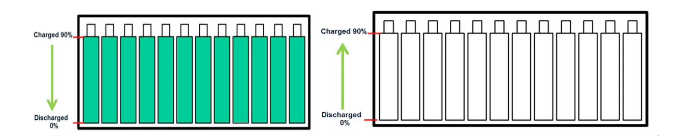
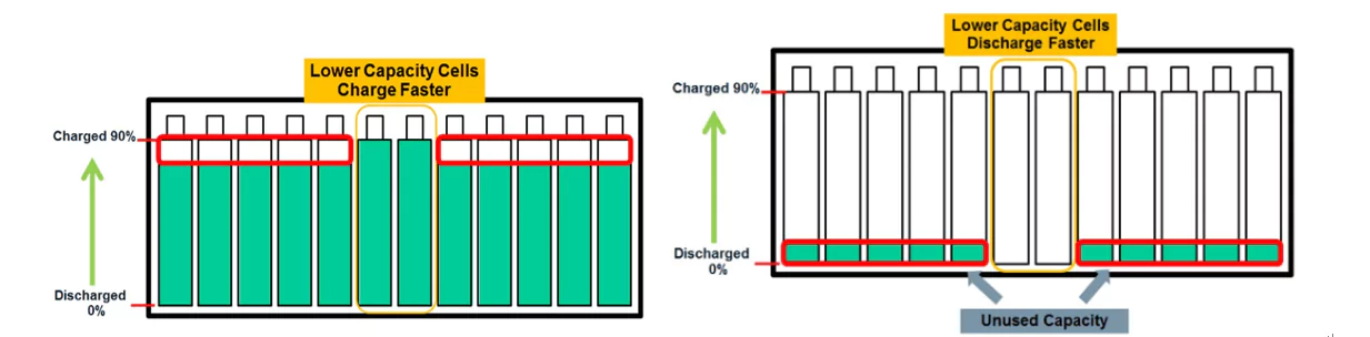
  • Cell Balancing: Lithium-ion battery packs consist of multiple cells connected in series. Ideally, all cells should discharge and charge at the same rate. However, slight manufacturing variances or uneven usage can lead to imbalances. The BMS PCB can employ cell balancing to address this. It monitors individual cell voltages and, if a discrepancy arises:

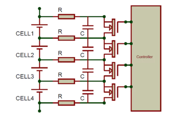
    • It activates passive balancing circuits that redistribute charge from higher voltage cells to lower voltage ones, bringing them closer to a balanced state.
    • In some advanced systems, active balancing might be used, involving dedicated circuits to transfer charge more efficiently.
  • Current Management: The BMS PCB plays a crucial role in managing the current flow within the battery pack:

    • Over-current Protection: If the charging or discharging current exceeds a safe limit, the BMS PCB can intervene by:
      • Limiting the current electronically using MOSFETs (Metal-Oxide-Semiconductor Field-Effect Transistors).
      • Disconnecting the battery from the charger or load entirely in severe cases.
    • Short-Circuit Protection: In case of a short circuit within the battery pack, the BMS PCB can quickly disconnect the battery to prevent damage from excessive currents and overheating.

How to check if BMS is working?

Protection:

The BMS PCB implements various safeguards to shield the battery from harmful conditions:

  • Overcharge Protection: Lithium-ion batteries can be permanently damaged by excessive voltage during charging. The BMS PCB monitors the total pack voltage and individual cell voltages. If the voltage reaches a pre-set overcharge threshold:

    • It can terminate the charging process by disconnecting the battery from the charger.
    • In some cases, it might activate safety features within the charger itself.
  • Over-discharge Protection: Deep discharging a lithium-ion battery below its minimum safe voltage can significantly reduce its lifespan or even cause permanent damage. The BMS PCB monitors the total pack voltage and individual cell voltages. If the voltage falls below a pre-set over-discharge threshold:

    • It can disconnect the load to prevent further discharge.
    • It might issue a warning or shut down the device entirely.
  • Temperature Protection: Extreme temperatures can degrade battery performance and safety. The BMS PCB monitors the battery pack’s temperature. If the temperature exceeds a safe limit:

    • It might reduce the charging or discharging current to prevent further heating.
    • In severe cases, it can completely disconnect the battery to allow it to cool down.

By implementing these control and protection features, the BMS PCB ensures the battery operates within safe voltage, current, and temperature ranges. This safeguards the battery from damage, extends its lifespan, and maximizes its performance

  • A microcontroller on the PCB analyzes the data based on pre-programmed safety thresholds.
  • If any parameter exceeds the safe limits (e.g., the voltage gets too high or low, the temperature rises excessively), the microcontroller takes corrective actions:
    • It can disconnect the battery from the charger or load (depending on charging/discharging) using electronic switches (MOSFETs).
    • In some cases, it might initiate cell balancing to equalize voltages between cells in the pack.

Overall, the BMS PCB works to:

  • Ensure safe operation of the battery by preventing overcharging, over-discharging, and overheating.
  • Maximize battery lifespan by keeping it within optimal operating conditions.
  • Improve battery performance by managing current flow and cell balancing.

How to check if BMS is working?

The complexity of a BMS PCB can vary depending on the application. Some basic PCBs might just focus on essential protection features, while more advanced ones can offer additional functionalities like data logging and communication with external systems.

What is Transformer?CategoriesNews

What is Transformer?

What is a Transformer?

What is Transformer?, transformer is an electrical device that uses electromagnetic induction to pass an alternating current (AC) signal from one electric circuit to another, often changing (or “transforming”) the voltage and electric current. Transformers do not pass direct current (DC), and can be used to take the DC voltage (the constant voltage) out of a signal while keeping the part that changes (the AC voltage). In the electrical grid transformers are key to changing the voltages to reduce how much energy is lost in electrical transmission.

Transformers change the voltage of the electrical signal coming out of the power plant, usually increasing (also known as “stepping up”) the voltage. Transformers also reduce (“step down”) the voltage in substations, and as distribution transformers.[2] Transformers are also used as a part of devices, like current transformers.

How transformers work

It often seems surprising that a transformer keeps the total power the same when the voltage goes up or down. One must keep in mind that when the voltage goes up, the current goes down:

What is Transformer?

Transformers use electromagnetic induction to change the voltage and current. The transformer action, known as transformer action, explains how the transformer converts an AC signal from its primary to its secondary component. When an AC signal is applied to the primary coil, the changing current causes a magnetic field to change (get bigger or smaller). This changing magnetic field (and associated magnetic flux) will pass through to the secondary coil inducing a voltage across the secondary coil, thereby effectively coupling the AC input from the primary to secondary component of the transformer. The voltage applied to the primary component will also be present in the secondary component.

As mentioned before, transformers do not allow DC input to flow through. This is known as DC isolation. This is because a change in current cannot be generated by DC; meaning that there is no changing magnetic field to induce a voltage across the secondary component.

What is Transformer?

What is Transformer?
Transformer
What is Transformer?

Figure 1. A simple operating transformer. Currently comes with a voltage. The current passes through the windings creating magnetic flux in the iron core. This flux is traveling through loops of wire on the other circuit. This creates a current and a voltage difference in the second circuit of. The electric power () stays the same.

The fundamental principle that allows transformers to change the voltage of alternating current is the direct relationship between the ratio of loops of wire in the primary winding to the secondary winding and the ratio of the primary voltage to the output voltage. The ratio between the number of turns (or loops) in the primary coil to the number of turns in the secondary coil is known as the turns ratio. The turns ratio establishes the following relationship with voltage:

  • Please make a note of the following text: “Number of turns in the primary coil.”
  • Please remember the following text: “Number of turns in the secondary coil.”
  • Certainly! Here is the revised text: “Please remember the following text: “
  • Certainly! Here is the revised text: “Please remember the following text: “
  • Please remember the following text: “Voltage across the secondary.”
  • “Please remember the following text: ‘Current through the primary.'”

From this equation, if the number of turns in the primary coil is greater than the number of turns in the secondary coil (), then the voltage across the secondary coil will be less than in the primary coil. This is known as a “step-down” transformer, because it lowers, or steps down, the voltage. The table below shows common types of transformers used on the electrical grid.

What is Transformer?

Transformer Type Voltage Turns ratio Current Power
Step down input (primary) voltage > output (secondary) voltage p>s p<s p=s
Step up input (primary) voltage < output (secondary) voltage p<s p>s p=s
One-to-one input (primary) voltage = output (secondary) voltage p=s p=s p=s

What is Transformer?

The one-to-one transformer will have equal values for everything and is used mainly to provide DC isolation.

step-down transformer will have a higher primary voltage than secondary voltage, but a lower primary current value than its secondary component.

In the case of the step-up transformer, the primary voltage will be lower than the secondary voltage, meaning a greater primary current than the secondary component.

What is Transformer?

What is Transformer?

Efficiency

Under ideal conditions the voltage and current change by the same factor for any transformer, which explains why the primary power value is equal to the secondary power value for each case in the above table. As one value decreases the other increases to keep at a constant equilibrium power level.

Transformers can be extremely efficient. High-power transformers can reach the 99% mark of efficiency, as a result of successes in minimizing transformer losses. However, a transformer will always output a slightly lower power than its input, as losses cannot be eliminated. There is some transformer impedance.

To learn more about transformers please see hyperphysics.

What are the efficiency losses of transformers?CategoriesTechnology Blogs

What are the efficiency losses of transformers?

What are the efficiency losses of transformers?

In this article, we will learn about the four main types of transformer losses and calculations for finding the efficiency of a transformer.

What are the efficiency losses of transformers?

What are the efficiency losses of transformers?
Transformer

Transformers, like all devices, are not perfect. While ideal transformers do not have losses, real transformers have power losses. A transformer’s output power is always slightly less than the transformer’s input power. These power losses end up as heat that must be removed from the transformer. The four main types of loss are resistive loss, eddy currents, hysteresis, and flux loss.

What are the efficiency losses of transformers?

Resistive Loss:-

Resistive loss, I2R loss, or copper loss, is the power loss in a transformer caused by the resistance of the copper wire used to make the windings. Since higher frequencies cause the electrons to travel more toward the outer circumference of the conductor (skin effect), electrical disturbances called harmonics have the effect of reducing the wire size and increasing resistive loss. These losses are the same as the power losses in any conductor and are calculated as follows:

𝑃=𝐼2𝑅

where

P = power (in W)

I = current (in A)

R = resistance (in Ω)

For example, if a transformer primary is wound with 100′ of #12 copper wire that carries 15 A, what is the resistive loss in that coil?

The resistance of #12 copper wire is 1.588 Ω/1000′ at room temperature. Therefore, the resistance of 100′ of the wire is 0.1588 Ω.

𝑃=𝐼2𝑅=152×0.1588=35.7𝑊

The transformer’s primary wiring consumes 35.7 W of power that is wasted as heat. If the transformer is not cooled properly, this heat increases the temperature of the transformer and the wires. This increased temperature causes an increase in the wire resistance, and the voltage drops across the conductor. This loss varies with the current and is always present in the primary when it is energized. The secondary sees very little loss of this type when unloaded.

Note

Changes that an electric utility makes to power delivery can affect the operation of in-plant transformers. A new area substation can boost the delivered voltage. New factories or commercial buildings may increase the local load and decrease the voltage available. The taps on in-plant transformers may need to be adjusted.

What are the efficiency losses of transformers?

Eddy Current Loss:-

Eddy current loss is power loss in a transformer or motor due to currents induced in the metal parts of the system from the changing magnetic field. Any conductor that is in a moving magnetic field has a voltage and current induced in it. The iron core offers a low reluctance to the magnetic flux for mutual induction. The magnetic flux induces current at right angles to the flux. This means that current is induced across the core. This current causes heating in the core. The heat produced by eddy currents increases as the square of the frequency. For example, the third harmonic (180 Hz) has nine (32) times the heating effect of the fundamental (60 Hz) frequency.

Constructing the core from thin sheets of iron laminated together can minimize this loss. The thin sheet-iron layers shorten the current path and minimize the eddy currents (see Figure 1). Each sheet is coated with an insulating varnish that forces these currents to only flow within individual laminations. This reduces the overall eddy currents in the entire core. These thin sheets are manufactured from silicon-iron or nickel-iron alloys that can be magnetized more readily than pure iron. The use of alloy cores also improves the age resistance of the core. The sheets are often made from 29-gauge alloy, which is only 0.014′′ thick.

Transformer Losses and Efficiency

What are the efficiency losses of transformers?

Hysteresis Loss:-

Hysteresis loss is loss caused by the magnetism that remains (lags) in a material after the magnetizing force has been removed. Magnetic domains are small sections of a magnetic material that act together when subject to an applied magnetic field. Magnetic domains have magnetic properties and move in iron when subjected to a magnetic field. When the iron is subjected to a magnetic field in one polarity, the magnetic domains will be forced into alignment with the field. When the polarity changes twice each cycle, power is consumed by this realignment, and this reduces the efficiency of the transformer. This movement of the molecules produces friction in the iron, and thus heat is a result. Harmonics can cause the current to reverse direction more frequently, leading to more hysteresis loss. Hysteresis is reduced through the use of highly permeable magnetic core material.

What are the efficiency losses of transformers?

Flux Loss:-

Flux loss occurs in a transformer when some of the flux lines from the primary do not pass through the core to the secondary, resulting in a power loss. There are two main reasons for flux lines to travel through the air instead of through the core. First, the iron core can become saturated so that the core cannot accept any more flux lines. The lines of flux then travel through the air and are not cut by the secondary. Second, the ratio of the reluctance of the air and the core in the unsaturated region is typically about 10,000:1. This means that for every 10,000 lines of flux through the core, there is 1 line of flux through the air. Flux loss is generally small in a well-designed transformer.

Transformer Losses and Efficiency

Transformer Efficiency:-

The ratio of a transformer’s output power to its input power is known as transformer efficiency. The effect of transformer losses is measured by transformer efficiency, which is typically expressed as a percentage. The following formula is used to measure transformer efficiency:

𝜂=𝑃𝑂𝑈𝑇𝑃𝐼𝑁

where

η = transformer efficiency (in %)

POUT = transformer output power (in W)

PIN = transformer input power (in W)

Example: What is the efficiency of a transformer that has an output power of 1500 W and an input power of 1525 W?

𝜂=𝑃𝑂𝑈𝑇𝑃𝐼𝑁=1500𝑊1525𝑊=98.36

The efficiencies of power transformers normally vary from 97 to 99 percent. The power supplied to the load plus resistive, eddy current, hysteresis, and flux losses must equal the input power. The input power is always greater than the output power.

What are the efficiency losses of transformers?

Essential Maintenance Tips for Your Lithium Battery InverterCategoriesNews

Essential Maintenance Tips for Your Lithium Battery Inverter

Essential Maintenance Tips for Your Lithium Battery Inverter

Essential Maintenance Tips for Your Lithium Battery Inverter


As we are moving towards a technologically advanced world, it has become difficult to stay without electricity even for a brief period. However, there is a powerful device that can guarantee our ever-increasing requirement for energy. One such device is a lithium battery inverter. It is a scientific marvel that lets us avoid power outages.

Power cuts are very common in India. But what if your appliances still run during a power cut? This can be achieved through the use of a lithium battery inverter. It is a dependable device that ensures your life keeps pace with an unbroken supply of electricity. Let’s learn more about it to realize its full potential.

Essential Maintenance Tips for Your Lithium Battery Inverter

General Maintenance Tips for Lithium Battery Inverters

Maintaining your lithium battery inverter doesn’t need to be a difficult task. However, there are some maintenance tips that you need to follow to increase its efficiency. Following these tips may help your inverter last a long time and function at its best if you use it with care. Here are some of the most important tips:

Regular Inspection and Cleaning: Check your inverter frequently for any signs of wear, dust, or debris. Gently wipe off the outside surfaces with a clean cloth or brush to keep them looking pristine.

Essential Maintenance Tips for Your Lithium Battery Inverter

Ensuring Proper Ventilation and Temperature Control: Lithium battery inverters require ventilation and a cool environment. Avoid overheating, and make sure you offer sufficient ventilation. You should also keep the inverter out of direct sunlight and small places with poor airflow.

Essential Maintenance Tips for Your Lithium Battery Inverter

Handling and Storing the Inverter Correctly: Be gentle while handling and storing your inverter. Do not drop or handle it carelessly, as this could harm its internal parts. Store it in a cool, dry location.

Essential Maintenance Tips for Your Lithium Battery Inverter

Extending Battery Lifespan

Lithium battery inverters last for a very long time. However, there are some special tips that you can follow to make it last even longer. Here are some suggestions to increase the longevity of your lithium battery inverter so that it keeps functioning properly over time:

Limit the number of times the battery receives a full charge to protect it. Choose partial charge cycles whenever you can to give your battery a break and extend its life.

A battery’s biggest adversary can be extremely high temperatures. Protect your lithium battery inverter from extreme heat and cold to function in a suitable temperature range. Keep in mind that a happy battery is cool.

Activate hibernate mode on your inverter if you anticipate it won’t be used for an extended period. Doing this will prevent overcharging or discharging too much throughout its idle period, ultimately maintaining its vitality.

Essential Maintenance Tips for Your Lithium Battery Inverter

Essential Maintenance Tips for Your Lithium Battery Inverter

Safety Precautions

Another crucial factor is safety. A lithium battery inverter is usually trustworthy, but there are some measures that you can take to make them even safer. When working with your lithium battery inverter, keep in mind the following safety precautions:

Know the Hazards: Make sure you know of any potential concerns related to lithium batteries. Mishandling these devices might make them volatile. Familiarize yourself with the dos and don’ts to keep you and your inverter safe.

Handle with Care: Carefully handle your lithium battery. The sensitive components inside can be harmed by needless shaking or hard handling. Do it gently!

Fire Safety 101: Avoid covering your inverter with anything restricting the airflow. Make sure it has enough ventilation. Keep anything combustible far away from it.

Conclusion

Careful maintenance of lithium battery inverters keeps your energy flowing smoothly. You may keep your inverter charged efficiently by paying attention to these tips and tricks. Remember that a little care goes a long way to keep your power up and running! Therefore, don’t hesitate – get an inverter and take control. If you are looking for an inverter, visit the Su-vastika website. Su-vastika is a company that provides very efficient lithium battery inverters that can fulfill your needs.

The Importance of Inverter Battery Blast ProtectionCategoriesNews

The Importance of Inverter Battery Blast Protection

The Importance of Inverter Battery Blast Protection

बम की तरफ फटेगी Inverter की Battery ! एक गलती से उड़ जाएंगे इसके परखच्चे

Inverter Battery Blast Protectionइन्वर्टर आपके लिए जितना मददगार साबित होता है ये उतना ही खतरनाक भी हो सकता है, दरअसल इन्वर्टर को अच्छे रख-रखाव की जरूरत पड़ती है. सही रख-रखाव के अभाव में इन्वर्टर की बैटरी दम तोड़ने लगती है. इतना ही नहीं कई बार तो बैटरी की स्थिति इतनी ज्यादा बिगड़ जाती है कि इसमें धमाका हो जाता है. ये धमाका बेहद ही खतरनाक साबित हो सकता है. ऐसा ना हो इस बात का ध्यान रखते हुए आज हम आपको बताने जा रहे हैं कि कैसे आप इन्वर्टर बैटरी ब्लास्ट को रोक सकते हैं.

The Importance of Inverter Battery Blast Protection

पानी रीफिल करना है जरूरी 

45 दिन में करें चेक

इन्वर्टर बैटरी में पानी भरना न भूलें, क्योंकि पानी सूखने से बैटरी को नुकसान हो सकता है और आग लगने का खतरा भी बढ़ सकता है. इस्तेमाल के साथ पानी का लेवल कम हो जाता है, इसलिए अगर इन्वर्टर का इस्तेमाल बार-बार किया जा रहा है तो हर 45 दिनों में इसे चेक करते रहें.

डिस्टिल्ड वॉटर होता है सबसे अच्छा

इन्वर्टर की बैटरी भरने के लिए डिस्टिल्ड वॉटर का उपयोग करना सबसे अच्छा है. नल के पानी या आरओ द्वारा शुद्ध किए गए पानी में अभी भी अशुद्धियां या खनिज हो सकते हैं जो बैटरी को नुकसान पहुंचा सकते हैं.

इन ब्लास्ट के कुछ मुख्य कारण हैं:

  • अत्यधिक चार्जिंग: यदि बैटरी को उसकी क्षमता से अधिक चार्ज किया जाता है, तो इससे गैसों का निर्माण हो सकता है जो विस्फोट का कारण बन सकता है।
  • अत्यधिक तापमान: अत्यधिक तापमान पर बैटरी का उपयोग करने से भी विस्फोट का खतरा बढ़ जाता है।
  • खराब वेंटिलेशन: यदि बैटरी को ठीक से हवादार नहीं किया जाता है, तो गैसें जमा हो सकती हैं और विस्फोट का कारण बन सकती हैं।
  • क्षतिग्रस्त या पुरानी बैटरी: क्षतिग्रस्त या पुरानी बैटरी विफल होने और विस्फोट का कारण बनने की अधिक संभावना रखती हैं।

इन्वर्टर बैटरी ब्लास्ट को रोकने के लिए आप कुछ कदम उठा सकते हैं:

  • उच्च गुणवत्ता वाली बैटरी का उपयोग करें: एक प्रतिष्ठित निर्माता से नई, उच्च गुणवत्ता वाली बैटरी खरीदें।
  • सही चार्जर का उपयोग करें: अपनी बैटरी के लिए निर्माता द्वारा अनुशंसित चार्जर का उपयोग करें।
  • अपनी बैटरी को ठंडी और सूखी जगह पर रखें: सीधे धूप या अत्यधिक तापमान से बचें।
  • अपनी बैटरी को नियमित रूप से वेंटिलेट करें: सुनिश्चित करें कि बैटरी क्षेत्र में हवा का प्रवाह अच्छा है।
  • अपनी बैटरी की नियमित रूप से जांच करवाएं: एक योग्य इलेक्ट्रीशियन से अपनी बैटरी की जांच हर छह महीने में करवाएं।
  • क्षतिग्रस्त या पुरानी बैटरी बदलें: यदि आपकी बैटरी क्षतिग्रस्त या पुरानी है, तो उसे तुरंत बदल दें।

इन युक्तियों का पालन करके, आप इन्वर्टर बैटरी ब्लास्ट के खतरे को कम कर सकते हैं और अपने घर और परिवार को सुरक्षित रख सकते हैं।

इन्वर्टर बैटरी ब्लास्ट एक गंभीर खतरा है, लेकिन इसे उचित सावधानी और रखरखाव के साथ रोका जा सकता है।

इन्वर्टर बैटरी के पानी को रिफिल करने के बारे में:

  • नियमित रूप से पानी का स्तर जांचें: बैटरी के लेबल पर दिए गए निर्देशों का पालन करें और यह सुनिश्चित करने के लिए नियमित रूप से पानी का स्तर जांचें कि यह “मिनिमम” और “मैक्सिमम” स्तर के बीच में है।
  • केवल डिस्टिल्ड वॉटर का उपयोग करें: नल के पानी या आरओ पानी में अशुद्धियां हो सकती हैं जो बैटरी को नुकसान पहुंचा सकती हैं। डिस्टिल्ड वॉटर सबसे अच्छा विकल्प है।
  • धीरे-धीरे पानी भरें: बैटरी में पानी धीरे-धीरे और सावधानी से भरें, यह सुनिश्चित करते हुए कि यह ओवरफ्लो न हो।
  • पानी भरने के बाद टर्मिनलों को साफ करें: पानी भरने के बाद, किसी भी अतिरिक्त पानी को पोंछने के लिए एक सूखे कपड़े का उपयोग करें

Inverter batteries are undeniably useful, but like many things, they require proper care to function safely. Here’s how to protect yourself from inverter battery blasts:

Understanding the Risks:

  • Overcharging: When a battery receives more power than it can handle, it can generate excessive gas and potentially explode.
  • Extreme Temperatures: Heat weakens batteries and increases the risk of explosions. Keep your battery in a cool, dry area.
  • Poor Ventilation: Batteries release gases during operation. If the area isn’t well-ventilated, these gases can accumulate and ignite.
  • Damaged or Old Batteries: Worn-out batteries are more susceptible to failure and explosions.

Safety Measures:

  • High-Quality Battery: Invest in a new, high-quality battery from a reputable brand.
  • Correct Charger: Use the charger recommended by the battery manufacturer.
  • Cool, Dry Location: Place your inverter and battery in a cool, dry area with good air circulation. Avoid direct sunlight.
  • Regular Inspection: Have a qualified electrician inspect your battery every six months.
  • Timely Replacement: Replace damaged or old batteries promptly.

Additional Safety Tips:

  • Keep Out of Reach: Store your battery away from children and pets.
  • No Smoking or Flames: Open flames and smoking near the battery are fire hazards.
  • Unusual Signs: If you notice any strange odors or sounds from your battery, stop using it immediately and consult a qualified electrician.

Following these precautions can significantly reduce the risk of inverter battery explosions and keep your home safe.

Refilling Battery Water (if applicable):

  • Check Water Level Regularly: Follow the battery’s instructions to maintain the water level between the minimum and maximum indicators.
  • Only Distilled Water: Use distilled water only. Regular tap water or RO water can contain impurities that harm the battery.
  • Slow and Careful Refilling: Refill the battery slowly and carefully to avoid overflow.
  • Clean Terminals After Refilling: Use a dry cloth to remove any excess water and clean the battery terminals.
Unleashing the Power: The Role of Battery Management SystemsCategoriesNews

Unleashing the Power: The Role of Battery Management Systems

The Brain Behind the Battery: Critical Role of Battery Management System in Residential Energy Storage

Unleashing the Power: The Role of Battery Management Systems

1. Introduction

2. What is a Battery Management System (BMS) and how Does It Work?

3. Structure and Components of a BMS

4. Key Functions of a BMS

5. Why a BMS is Critical for Residential Storage

6. Conclusion

Unleashing the Power: The Role of Battery Management Systems

Unleashing the Power: The Role of Battery Management Systems
Understanding the Function of Battery Management System (BMS)

Unleashing the Power: The Role of Battery Management Systems

1. Introduction

The growing deployment of lithium-ion batteries for residential energy storage is driven by their unmatched performance compared to lead-acid batteries. However, fully utilizing the capabilities of lithium-ion chemistry requires sophisticated battery management to ensure safe, optimal, and enduring operation. This is where Sunwoda Energy’s advanced built-in battery management system (BMS) technology comes into play.

Understanding what a BMS is and how it works is vital for both customers and installers as lithium-ion batteries continue to dominate in residential storage systems. This article will offer an in-depth look at lithium-ion battery management technology and why it is important for residential applications.

2. What Is a Battery Management System (BMS) And How Does It Work?

A Battery Management System (BMS) is an electronic system that acts like a babysitter for a rechargeable battery, whether it’s a single cell or a whole pack.

Here’s what a BMS typically does:

  • Monitors the battery: The BMS keeps an eye on things like voltage, temperature, current flow, and how much charge is left in the battery (state of charge).
  • Protects the battery: The BMS makes sure the battery operates within safe limits by preventing things like overcharging, over-discharging, overheating, and short circuits. This can extend the battery’s lifespan and keep it from being damaged.
  • Optimizes performance: A BMS can help get the most out of a battery by managing how it’s charged and discharged. This can improve the battery’s range and efficiency.
  • Reports battery status: The BMS can communicate with other devices, like a laptop or electric car controller, to let them know how the battery is doing.

Unleashing the Power: The Role of Battery Management Systems

Some BMS systems are more complex than others. A simple battery pack for a laptop might just have a basic protection circuit module (PCM) to prevent overcharging. More complex BMS systems, especially for things like electric vehicles, can do a lot more sophisticated monitoring and balancing to keep the battery healthy and functioning well.

Unleashing the Power: The Role of Battery Management Systems
Lithium battery bank with BMS

Unleashing the Power: The Role of Battery Management Systems

Unleashing the Power: The Role of Battery Management Systems

Unleashing the Power: The Role of Battery Management Systems

The decisions on charge or discharge rates made by the BMS are based on estimated battery State of charge (SOC), battery capacity, impedance, voltage, current, temperature measurements, load demands, etc. The primary function of the BMS is to control the discharge of a battery, whereas its primary goal is to ensure that the battery is operating within the operational limits and thereby protect the cells during discharging and charging. Keeping track of battery SOC is one of the features of the BMS. These could indicate the user and control the charging and discharging processes.

3. Structure and Components of a BMS


Unleashing the Power: The Role of Battery Management Systems

A Battery Management System (BMS) is made up of several key components that work together to manage the battery. These components can be generally classified into two categories: hardware and software.

Hardware Components:

  • Sensors: These are devices that monitor the various aspects of the battery’s operation. Common sensors include:
    • Voltage sensors: measure the electrical potential across the battery terminals.
    • Current sensors: measure the flow of current into or out of the battery.
    • Temperature sensors: measure the temperature of the battery cells.
  • Microcontroller Unit (MCU): This is the brain of the BMS. It collects data from the sensors, processes it, and makes decisions about how to manage the battery based on the BMS algorithms.
  • Power Management Circuit (PMC): This circuit controls the flow of power into and out of the battery. It can turn the battery on or off, and it can limit the amount of current that can be drawn from the battery.
  • Communication Interface: This allows the BMS to communicate with other devices, such as a laptop or electric car controller. Common communication interfaces include CAN bus, I2C, and UART.
    Unleashing the Power: The Role of Battery Management Systems

Software:

  • Battery Management System Algorithms: These are the computer programs that tell the MCU what to do with the data it receives from the sensors. The BMS algorithms determine things like:
    • The state of charge (SOC) of the battery.
    • The state of health (SOH) of the battery.
    • Whether the battery needs to be charged or discharged.
    • The appropriate charging and discharging currents and voltages.
  • Safety Features: The BMS software also includes safety features that can protect the battery from damage. These features can include:
    • Overcharge protection
    • Over-discharge protection
    • Over-temperature protection
    • Over-current protection
    • Short circuit protection

The specific hardware and software components of a BMS will vary depending on the application. A simple battery pack for a consumer electronic device will have a less complex BMS than a large battery pack for an electric vehicle. However, all BMS systems share the same basic goal: to safely and efficiently manage the battery.

Unleashing the Power: The Role of Battery Management Systems

4. Key Functions of a BMS

Unleashing the Power: The Role of Battery Management Systems

• Cell monitoring

The BMS continuously monitors the current, voltage, and temperature of each individual cell in the battery pack. This is crucial for detecting imbalances among cells. If some cells have higher values than the set value, then the BMS can take corrective actions, such as bleeding off excess energy from the overcharged cells or limiting charging to prevent overvoltage.

• External communication function

The BMS supports 485 communication and CAN communication for external communication. By connecting the CAN communication upper computer, the BMS can achieve remote monitoring, remote communication, and remote adjustment functions. The function explanation is as follows:

Remote monitoring: Obtain battery pack operation information, such as SOC, SOH, voltage, temperature, etc.; Remote communication: Obtain the operating status of the battery pack, such as alarm protection status, charging and discharging status, etc.; Remote adjustment: configuration of functional parameters.

• Cell balancing

Every cell in a passive balancing system is linked to a bleed resistor or balancing resistor. The balancing resistor lowers the voltage by allowing a small amount of energy to discharge when a cell’s voltage hits a certain threshold. This procedure continues until all cell voltages are balanced.

Unleashing the Power: The Role of Battery Management Systems

Unleashing the Power: The Role of Battery Management Systems

When the battery pack is charged without balancing, the weaker cells reach their maximum capacity before the stronger cells. Weak cells restrict the system’s runtime, even when some cells may still have a significant amount of capacity. 5% of the capacity is wasted due to a mismatch in cells. This can be an excessive amount of energy wasted with big batteries.

Unleashing the Power: The Role of Battery Management Systems


In the circuit example below, a MOSFET connects each of the four cells to two bypass resistors. The controllers measure the four cells’ voltages, activating the MOSFET in the cell whose voltage is higher than the others. That specific cell discharges through the resistors when the MOSFET is switched on. We can forecast how much charge the cell will lose since we know the resistance values. The capacitor acts as a voltage spike filter during switching and is connected in parallel with the cell.

Unleashing the Power: The Role of Battery Management Systems


Note: Charge equalization On and off based on the voltage of the unit, the equalization current is 50mA.

• Over voltage/Under Voltage Protection

a. Discharge under voltage protection:

When discharging, the voltage of any single cell is lower than the protection value, the over-discharge protection will be started, and the battery will show an alarm signal. When the voltage of all cells is recovered to the range of released value, the protection is removed.

b. Charging over-voltage protection:

During charging, when the total voltage of the battery pack or the voltage of any single cell reaches the protection value, the system stops charging. When the total voltage and the single voltage return to the released value range, the protection will be released.

• Current Protection

a. Charging Over Current Protection:

When the charging current is more than the protection value, it will automatically enter into the charging current limit state(5±1A). The current limiting module automatically runs for 30 minutes to recover; switch to discharge; restart.

b. Discharging Over Current Protection:

When the discharge current is more than the protection value, the battery will start charging recovery, restart recovery, automatic recovery after 1 minute, and trigger 3 protection locks in 1 hour.

• Temperature Protection

a. Charge low/high-temperature protection:

During charging, when the battery temperature exceeds the range of – 10 ℃ ~ + 55 ℃, the system starts the charging temperature protection, stops charging, recovers to the rated return value, and then the protection is released.

b. Discharge low/high-temperature protection:

During discharging, when the battery temperature exceeds the range of -20℃~+60℃, the system starts the discharging temperature protection, stops discharging, recovers to the rated return value, and then the protection is released.

• Three levels of circuit break protection (permanent hardware failure)

When a short circuit failure occurs in the main circuit of the BMS board, severe overvoltage, under voltage, overcurrent, and overheating of the battery cell can cause the controllable fuse in the charging and discharging circuit to permanently blow, and the BMS cannot be restored.

Unleashing the Power: The Role of Battery Management Systems

5. Why a BMS is Critical for Residential Storage?

The BMS is essential to getting the most out of your home energy storage system. Here are some key reasons it’s so important:

• Safety: The BMS acts as the first line of defense, preventing damage from improper operation that could potentially lead to catastrophic battery failure or fire.

• Performance: Active cell balancing and charge/discharge control enable every bit of the battery’s capacity to be used efficiently.

• Longevity: By maintaining safe operating conditions and evenly using all cells, the BMS allows the battery to achieve its designed lifespan.

• Accuracy: Precise state of charge and life estimations from the BMS allow the overall system to operate optimally.

• Reliability: Continuous monitoring and safety protections give peace of mind that the system will operate as intended.

Unleashing the Power: The Role of Battery Management Systems

6. Conclusion

In conclusion, integrating smart battery management technology is essential for maximizing the performance and ensuring the safety of lithium-ion batteries in home storage. Sunwoda Energy, a prominent player in the field of lithium iron phosphate (LFP) battery solutions, specializes in the development of advanced batteries with intelligent Battery Management System (BMS) technology tailored specifically to cater to the requirements of home energy storage applications. The BMS we have developed incorporates cutting-edge advancements in monitoring, processing, and control technologies to enhance the safety, lifespan, and efficiency of LFP batteries.

Sunwoda can exercise complete control over the whole production process, including the refinement of raw materials to the manufacturing of completed batteries. This enables us to provide residential users with lithium-ion batteries that are not only extremely reliable but also exhibit exceptional performance. The integration of Sunwoda’s lithium-ion cells, known for their superior performance, with modern Battery Management System (BMS) technology can fully use lithium-ion storage capabilities. This development paves the way for a sustainable future that relies on energy independence.

Unleashing the Power: The Role of Battery Management Systems

The Rise of Battery Storage: Overtaking Pumped HydroCategoriesNews

Save Money with the Top Solar Inverter Manufacturer in India

Save Money with the Top Solar Inverter Manufacturer in India

Save Money with the Top Solar Inverter Manufacturer in India, Solar power is a major component of the renewable energy sector. Extensive trials and investigations have proved that the sun provides more than enough energy to meet daily electrical requirements sustainably. All we need to do to harvest the full benefits is deploy clever energy solutions such as solar panels, batteries, and inverters. We have developed a list of the top solar inverter manufacturers who provide high-performance solar power solutions. Explore their whole line of inverters to make an informed decision and save money on electricity bills. 

Top-rated solar inverter manufacturers for 2023 in India 

Undoubtedly, a solar inverter is a crucial piece of equipment for running electronic devices at home and in the office. Here is a list of the top solar inverter manufacturers in India in 2023, which will assist you in selecting certified inverter manufacturers and making a better purchase. 

1. Su-vastika 

Save Money with the Top Solar Inverter Manufacturer in India

Su-vastika, a Government of India-recognized export house with many technology patents, is quickly rising as the leading provider of power backup and storage solutions. Offering a wide range of industry-leading solutions, including solar UPS, Energy Storage Systems (ESS), Lithium Battery (LiFePO4), Online UPS with Galvanic Isolation, Lift Inverters/UPS, Lithium Inverter/UPS, Solar Hybrid Inverters, and Solar PCU, the company is now a proud associate of names such as Tata, Schindler, Adani, and Raheja developers, among many others.

Su vastika has developed wall-mount lithium batteries for all of its devices, guided by Kunwer Sachdev. Known as the Inverter Man of India and Lithium Man of India, Kunwer Sachdev is the founder of Su-Kam and is now no longer with the company in any capacity. He is now mentoring Su-vastika where among many patented products, he has developed wall-mounted UPS/Inveterters. Customers will no longer have to deal with the issue of batteries taking up space on the floor or the destruction caused by spillage, which is typical of a lead-acid solution.

He has also brought the power of AI to Su-vastika’s products, which helps optimize its performance and give the best value to its customers.

Suvastika, a full-power storage solutions company known for ongoing innovation, is preparing India’s resilient energy storage systems for a sustainable future. Su-vastika, led by Khushboo Sachdev and mentored by Kunwer Sachdev, aims to disrupt and alter the solar energy and backup industries, and it is already halfway there. 

Save Money with the Top Solar Inverter Manufacturer in India

2. Microtek

Save Money with the Top Solar Inverter Manufacturer in India 

Microtek’s solar inverters, a known brand in the market, can help reduce electricity bills and maximize solar energy. Its on-grid and off-grid solar inverters are highly durable and require little maintenance to function well for years.

Save Money with the Top Solar Inverter Manufacturer in India

3. UTL Solar 

Save Money with the Top Solar Inverter Manufacturer in India


UTL Solar, a well-known company, consistently provides high-quality solar inverters with long-lasting performance. Its selection of on-grid and off-grid solar inverters includes the best alternatives for every application. So, you may be confident that you’ll find the best one for your needs. 

Save Money with the Top Solar Inverter Manufacturer in India

4. Livguard

Save Money with the Top Solar Inverter Manufacturer in India


Livguard’s solar inverters are well-known for their efficiency and longevity. As a result, they are the best alternative for installing in homes or offices. As a responsible and qualified producer, Livguard provides the finest possible attention to each customer and offers a wide choice of inverters to satisfy unique needs professionally. 

Save Money with the Top Solar Inverter Manufacturer in India

5. Luminous Power Technologies

Save Money with the Top Solar Inverter Manufacturer in India

Explore the extensive selection of Luminous solar inverters, both on and off the grid, with confidence. This manufacturer takes a proactive approach to enhancing the performance of inverters. As a result, its R&D teams are constantly experimenting with creative concepts and carefully implementing new inverters to make them more promising. 

Save Money with the Top Solar Inverter Manufacturer in India

 6. Lento India

Save Money with the Top Solar Inverter Manufacturer in India

Both on- and off-grid Lento solar inverters are well-known for their error-free production and strong performance with consistent electric current. Explore the extensive Lentor inverter selection to locate the best inverter for your needs quickly. 

Save Money with the Top Solar Inverter Manufacturer in India

Key Takeaways

Solar inverters are the most critical component of any residential or commercial solar power plant. Always use the highest-quality solar inverter because it is critical to reap the benefits of a consistent power supply and save significantly on pricey power bills with free electricity. Inverters come with a variety of specs and capabilities. Always speak with a qualified and experienced technician to purchase and install an appropriate inverter.

The Decreasing Price of Lithium-ion Batteries in IndiaCategoriesNews

Inverter/UPS Redefined: Suvastika Systems and the Role of AI

Inverter/UPS Redefined: Suvastika Systems and the Role of AI

Su-vastika under the mentorship of Mr. Kunwer Sachdev who is known as the Inverter Man of India and is the founder of the world-famous Su-kam is making Lithium-ion Inverters and UPS with AI-based technology which is getting famous in the Indian industry.

By making High Capacity Inverters based on Lithium-ion technology the company is creating waves all across.

Inverter/UPS Redefined: Suvastika Systems and the Role of AI

Inverter/UPS Redefined: Suvastika Systems and the Role of AI
Suvastika AI Based UPS Li 5500
  • Lithium Inverters: The text suggests lithium inverters, which combine inverters with lithium batteries, are seen as a promising technology for energy storage solutions. Lithium batteries offer advantages like high energy density, longer lifespan, and lower self-discharge compared to traditional lead-acid batteries.
  • Su-svastika and Mr. Kunwer Sachdev: The passage highlights Mr. Sachdev’s role in the inverter industry, with his prior success with Su-kam and the current focus on lithium-based inverters at Su-vastika. It seems Su-svastika is particularly interested in the following:
    • Heavy Duty 3 Phase Inverters: These are likely targeted for industrial applications where high power handling is needed.
    • Lift Inverters: Su-vastika might be a leader in lithium inverter solutions for elevators requiring reliable power backup.

Inverter/UPS Redefined: Suvastika Systems and the Role of AI

Inverter/UPS Redefined: Suvastika Systems and the Role of AI
Suvastika AI Based UPS Li 1100 VA Combo

Overall, the text paints a positive picture of Su-vastika’s work in lithium inverter technology, particularly under Mr. Sachdev’s leadership.

Here are some additional thoughts:

  • It would be interesting to learn more about Su-vastika’s specific patent filings and how their technology differentiates itself from competitors.
  • While lithium inverters hold promise, there are also challenges like cost and potential safety concerns. It would be good to see how Su-vastika addresses these aspects.

Inverter/UPS Redefined: Suvastika Systems and the Role of AI

Inverter/UPS Redefined: Suvastika Systems and the Role of AI
Suvastika Li ESS 4000

If you’d like to delve deeper, you could try searching for news articles or press releases from Su-vastika about their lithium inverter technology.

Why Compare Copper and Aluminium? A Detailed AnalysisCategoriesTechnology Blogs

How much loss does a transformer have?

How much loss does a transformer have?

  • Load Losses (Copper Losses): These losses occur due to the resistance of the transformer’s windings. As current flows through the coils, it encounters resistance, which dissipates some of the energy as heat.
  • Impact of Load: Unlike no-load losses, load losses vary depending on the amount of current flowing through the transformer. Higher load means higher current and consequently, greater I2R losses.
  • Minimizing Load Losses:
    • Conductor Material: Using conductors with low resistivity, like copper, helps reduce I2R losses.
    • Winding Design: Optimizing the design and cross-sectional area of the windings can also minimize resistance and hence, load losses.

How much loss does a transformer have?

Introduction to Transformer Losses

Transformers aren’t perfectly efficient and these losses are important to consider for their overall performance.

Here’s a breakdown of the two main types of transformer losses you mentioned:

  • Load Losses (Copper Losses): These losses occur due to the resistance of the wires in the transformer’s coils. As current flows through the coils, it encounters resistance, which dissipates some of the energy as heat. This loss increases with the square of the current flowing through the transformer.

  • No-Load Losses (Iron Losses): These losses happen within the transformer’s core due to the constantly changing magnetic field. There are two main contributors to iron losses:

    • Hysteresis Loss: When the magnetic field in the core reverses direction (which happens continuously with AC current), the core material experiences a tiny energy loss like a magnetic “memory” effect.
    • Eddy Current Loss: The changing magnetic field induces small circulating currents within the core itself, called eddy currents. These currents also create heat loss.

How much loss does a transformer have?

How much loss does a transformer have?

What Are Load Losses?

The amount of loss a transformer has depends on two main factors:

  1. Load Losses (I2R): This loss varies depending on the current flowing through the transformer.

  2. No-Load Losses (Iron Losses): These losses are constant and occur even when there’s no load on the transformer. They are produced by the characteristics of the core material and the fluctuating magnetic field.

Therefore, the total loss of a transformer is the sum of the load losses and the no-load losses.

Unfortunately, there’s no single answer to “how much loss” a transformer has because it depends on its specific design, size, and operating conditions. However, transformers are generally very efficient devices. Most well-designed transformers have a full load efficiency between 95% and 98.5%, meaning they lose only 1.5% to 5% of the input power.

Here are some additional points to consider:

  • Manufacturers specify the efficiency of a transformer at different load levels.
  • Choosing the right size transformer for the application is crucial. An oversized transformer will have higher no-load losses even when lightly loaded.

What Are No-load Losses?

No-load losses are caused by the magnetizing current needed to energize the core of the transformer and do not vary according to the loading on the transformer.

  • Cause: No-load losses are caused by the magnetizing current needed to establish the magnetic field in the core, independent of the actual load on the transformer.
  • Components: The main contributors are hysteresis and eddy current losses within the core laminations. These are material properties and occur even with no current drawn from the transformer.
  • Minimization: Using high-quality core steel with low hysteresis and eddy current losses, and employing thinner laminations, both help reduce these no-load losses.

How much loss does a transformer have?

Values of Transformer Losses (A and B Values)

The A and B factors are a crucial concept in evaluating the cost-effectiveness of transformers, especially for large users like utilities and industries. Here’s a breakdown of what you explained:

  • Importance of Transformer Losses: Transformer losses represent wasted energy and translate to additional costs over the transformer’s lifetime. Considering these losses is vital for choosing the most economical transformer.
  • A and B Factors: These factors are used to convert the future value of no-load and load losses into a present-day cost.
    • A Factor: Represents the equivalent present cost of future no-load losses, which are constant and depend on system capacity needs.
    • B Factor: Represents the equivalent present cost of future load losses, which vary with the amount of energy used.
  • Benefits of A and B Factors:
    • Allows for a more comprehensive economic comparison of transformers by considering both upfront cost and future energy losses.
    • Enables buyers to factor in the cost of supplying system capacity (no-load losses) and the cost of energy use (load losses).
  • Who Uses A and B Factors:
    • Electric utilities: They are heavily invested in transformers and optimizing their total cost of ownership is crucial.
    • Large industrial customers: Their high-energy usage makes considering future load losses significant.
  • Alternative for Smaller Users: Smaller end users often use life-cycle cost evaluation methods, which include upfront costs, maintenance costs, and potentially replacement costs over the life of the transformer.

How much loss does a transformer have?

When evaluating various transformer designs, the assumed value of transformer losses (A and B values) will contribute to determining the efficiency of the transformer to be purchased. Assuming a high value for transformer losses will generally result in the purchase of a more efficient unit; assuming a lower value of losses will result in the purchase of a less efficient unit. What value of losses should be assumed?

Unveiling Transformer Losses: An In-Depth Overview

The total owning cost (TOC) method provides an effective way to evaluate various transformer initial purchase prices and cost of losses. The goal is to choose a transformer that meets specifications and simultaneously has the lowest TOC. The A and B values include the cost of no-load and load losses in the TOC formula:

TOC = NLL x A + LL x B + C

Where,

TOC = capitalized total owning cost,
NLL = no-load loss in watts,
A = capitalized cost per rated watt of NLL (A value),
LL = load loss in watts at the transformer’s rated load,
B = capitalized cost per rated watt of LL (B value),
C = the initial cost of the transformer including transportation, sales tax, and other costs to prepare it for service.

How much loss does a transformer have?

How much loss does a transformer have?

What Is the A Value?

The A value is an estimate of the present value of future capital cost (nonload- dependent) items at a given point in time. It can vary over time as utilities re-evaluate their costs periodically. (In other words, the A value is the answer to the question, what is a watt of no-load loss over the life of the transformer worth to me today?) Even if there is no load, there is capital that is devoted to fixed capacity to generate, transmit, and distribute electricity, which contributes to the A value. The loading that may change daily on the transformer does not affect the no-load loss value. It is calculated using the following formula:

A = [SC + (EC x 8760)] x 0.001 / [FC]
= Cost of No-Load Loss in $/watt

Where,

SC = Annual Cost of System Capacity in $/kW-year (SC is the levelized annual cost of generation, transmission, and primary distribution capacity required to supply one watt of load to the distribution transformer coincident with the peak load).

EC = Energy Cost (EC is the levelized annual cost per kWh of fuel, including inflation, escalation, and any other fuel-related components of operation or maintenance costs that are proportional to the energy output of the generating units).

8,760 = hours per year

FC = Fixed Charge on capital per year (FC is the levelized annual revenue required to carry and repay the transformer investment obligation and pay related taxes, all expressed as a per-unit quantity of the original).

0.001 = conversion from kilowatts to watts.

How much loss does a transformer have?

What Is the B Value?

Similar to the way the A value is determined, the B value is an estimate of the present value of future variable, or load-dependent, cost items at a given point in time. (In other words, the B value is the answer to the question, what is a watt of load loss over the life of the transformer worth to me today?) The B value can also change over time as utilities reevaluate their costs periodically, but once determined, it is a constant value for a given transformer purchase. The cost of load losses, or B value, is calculated using the following formula:

B = [(SC x RF) + (EC x 8,760 x LF)] (PL) 2 (0.001) / (FC)
= Cost of Load Loss Cost $/watt

Where,

RF = Peak Loss Responsibility Factor (RF is the composite responsibility factor that reduces the system capacity requirements for load losses since the peak transformer losses do not necessarily occur at peak time).

LF = Annual Loss Factor (LF is the ratio of the annual average load loss to the peak value of the load loss in the transformer).

PL = Uniform Equivalent Annual Peak Load (PL is the Levelized peak load per year over the life of the transformer. Transformer life cycle is defined as the useful life of the asset and is usually assumed to be 30-35 years).

How much loss does a transformer have?

Specifying A and B Values

For custom-designed transformers, manufacturers optimize the design of the unit to the specified A and B values resulting in a transformer designed to the lowest total owning cost, rather than one designed for the cheapest first cost.

In situations where A and B values have not been determined (or the end user does not utilize or specify them), such as occur in commercial or small industrial applications, the suggested technique to maximize transformer efficiency is to obtain the no-load and full-load loss values of a specific transformer, in watts. This method is discussed in the article Transformer Life-Cycle Cost, elsewhere on this website.

How much loss does a transformer have?

https://lithiuminverter.in/uncategorized/how-lithium-lift-inverters-can-improve-elevator-ups-systems/

What is the function of lift inverter in elevator?CategoriesTechnology Blogs

What is the function of lift inverter in elevator?

What is the function of lift inverter in elevator?

Understanding the Lithium Lift Inverter: Backup Power for Elevators

How Lithium Lift Inverters can improve Elevator UPS systems:- A Lithium Lift Inverter, also known as an Elevator UPS or ERD (Emergency Rescue Device), is a system that provides backup power to elevators during power outages. The Lithium battery as a storage system has a lot of benefits for the Lift inverter/UPS as there are a lot of lead Acid batteries installed with the Lift UPS. The minimum number of batteries required for running the lift inverter/UPS is 10 numbers which takes a lot of space. The life of the Lead Acid batteries is reduced if so many batteries are used in series. The equalization of the lead Acid batteries in series is not possible. The Lift Inverter requires a higher discharge current as the Lift draws a very heavy current when starting the Lift so Lead Acid batteries have a limited life due to a higher discharge current. The Lift Inverter/UPS will have a longer life if used with the Lithium-ion battery bank.

What is the function of lift inverter in elevator?
Lift Inverter 30KVA

What is the function of lift inverter in elevator?

Here’s how it works:

Regular Operation:

  1. Main Power Supply: The elevator receives power from the main grid.
  2. Battery Charging: Simultaneously, the inverter charges the connected batteries, typically Lithium-ion (Li-ion) for their advantages.

Power Outage:

  1. Automatic Switch: When the main power goes out, the inverter automatically switches to battery mode within seconds.
  2. DC to AC Conversion: The inverter converts the DC power stored in the batteries into AC power.
  3. Elevator Operation: The converted AC power then runs the elevator motor, allowing it to continue functioning for the backup duration.

Power Restoration:

Automatic Switch Back: Automatic Switch Back in a Lithium Lift Inverter refers to the process of the inverter automatically returning to using grid power once the main power supply comes back online after an outage. Here’s a breakdown of the steps involved:

  1. Power Restored: The utility company restores power to the building’s main grid.
  2. Inverter Detection: The inverter continuously monitors the incoming grid voltage. It detects the presence of stable and appropriate voltage levels.
  3. Transfer Switch Activation: Upon detecting stable grid power, the inverter initiates the transfer switch. This switch is a built-in mechanism that acts as a gatekeeper for power flow.
  4. Grid Power Takes Over: The transfer switch disconnects the battery bank from the elevator motor and reconnects the motor to the incoming grid power.
  5. Inverter Monitoring: The inverter continues to monitor the grid voltage to ensure its stability. It remains in standby mode, ready to switch back to battery power if another outage occurs.
  6. Battery Recharging: The inverter automatically resumes charging the Lithium-ion batteries. This ensures they are fully charged and prepared for the next power cut.

How Lithium Lift Inverters can improve elevator UPS systems

Benefits of Automatic Switch Back:

  • Prevents Battery Drain: It avoids unnecessary use of battery power when grid power is available. This extends the overall lifespan of the batteries.
  • Reduced Maintenance: By minimizing reliance on battery power during normal operation, automatic switchback reduces the frequency of battery maintenance checks.
  • Cost-Effective: The inverter prioritizes using cheaper grid power, leading to lower electricity costs.
  • Seamless Transition: The switch back from battery to grid power happens automatically, ensuring a smooth and uninterrupted elevator operation for passengers.

Battery Recharging:

Lift inverters, especially those with Lithium-ion batteries, have built-in battery charging systems. Here’s a breakdown of how battery recharging works in a Lithium Lift Inverter:

What is the function of lift inverter in elevator?
Lithium Battery for Lift Inverter

Power Source:

  • The inverter utilizes the incoming main power supply (when available) for battery recharging.

Charging Stages:

  • Bulk Charge: During the initial stage, the inverter supplies a high current to the batteries to quickly bring them up to a predetermined voltage level.
  • Absorption Charge: Once the bulk charge stage is complete, the inverter reduces the charging current and maintains a constant voltage for a specific duration. This refines the charge and ensures the batteries are fully charged.
  • Float Charge: Finally, the inverter enters a float charge stage. Here, it supplies a low current to maintain the battery voltage at a specific level. This compensates for the battery’s self-discharge rate and keeps the batteries topped up for immediate use during a power outage.

Automatic Control:

  • The entire charging process is electronically controlled by the inverter’s internal circuitry.
  • The control system monitors factors like:
    • Battery voltage
    • Battery temperature
    • Charging current
  • Based on this information, the control system adjusts the charging stages and current levels to ensure a safe and efficient charging process.

What is the function of lift inverter in elevator?

Lithium-ion Battery Advantages:

  • Faster Charging: Compared to traditional lead-acid batteries, Lithium-ion batteries accept charge much quicker, allowing the inverter to replenish the batteries faster after an outage.
  • Reduced Heat Generation: Lithium-ion batteries generate less heat during charging, minimizing thermal stress on the batteries and extending their lifespan.
  • Longer Lifespan: With proper charging practices, Lithium-ion batteries can have a significantly longer lifespan compared to lead-acid batteries, reducing replacement costs.

Safety Features:

  • Modern inverters typically incorporate safety features like:
    • Overcharge Protection: Prevents the batteries from being overcharged, which can damage them.
    • Over-temperature Protection: Stops charging if the battery temperature exceeds a safe limit.
    • Current Limiting: Regulates the charging current to prevent excessive current flow that could damage the batteries.

What is the function of lift inverter in elevator?

Benefits of Lithium Lift Inverters: Lithium Lift Inverters offer several advantages over traditional inverters that use lead-acid batteries.

What is the function of lift inverter in elevator?
Lift inverter

Here’s a breakdown of the key benefits:

Enhanced Reliability and Performance:

  • Extended Battery Life: Lithium-ion batteries boast a significantly longer lifespan compared to lead-acid batteries. This translates to fewer replacements and lower maintenance costs over time.
  • Faster Charging: Lithium-ion batteries can recharge much quicker, ensuring the inverter is prepared for the next power outage with minimal downtime.
  • Deeper Discharge: They can discharge a larger portion of their stored energy compared to lead-acid batteries, providing more backup power for elevator operation during extended outages.
  • High Discharge Rate: Lithium-ion batteries can deliver high current bursts, ensuring the elevator motor has sufficient power to function smoothly during startup and operation.

What is the function of lift inverter in elevator?

Improved Efficiency and Cost Savings:

  • Reduced Energy Consumption: Lithium-ion batteries have a lower self-discharge rate compared to lead-acid batteries. This translates to less wasted energy and lower electricity costs for maintaining battery charge.
  • Space-Saving Design: Lithium-ion batteries are smaller and lighter than lead-acid batteries. This allows for a more compact inverter system, freeing up valuable space in the elevator machine room.
  • Lower Maintenance Costs: Due to their longer lifespan and lower self-discharge rate, Lithium-ion batteries require less frequent maintenance compared to lead-acid batteries.

What is the function of lift inverter in elevator?

Additional Advantages:

  • Environmentally Friendly: Lithium-ion batteries are considered a more environmentally friendly option compared to lead-acid batteries due to their reduced manufacturing footprint and lower heavy metal content.
  • Safer Operation: Modern Lithium Lift Inverters incorporate advanced safety features like overcharge and over-temperature protection to safeguard the batteries and prevent potential damage.
  • Seamless Operation: The automatic switch back and forth between grid power and battery power happens smoothly, ensuring uninterrupted elevator operation for passengers.

What is the function of lift inverter in elevator?

Overall, Lithium Lift Inverters provide a reliable and efficient backup solution for elevators, ensuring uninterrupted service during power outages.